Demo Model — UAV Autonomous Flight System
EXAMPLE · REFERENCE MODEL · model/
The repository ships with a complete UAV model under model/. It covers the full Syscribe element palette — structural architecture, behavior, requirements, test cases, constraints, calculations, allocations, and diagrams — and is used as the validator's self-test fixture.
This page is a guided tour. Browse the source on GitHub to read the raw Markdown files.
Namespace layout
Each directory is a package. Each .md file is an element.
model/
├── UAV/               — structural architecture (PartDefs, sub-systems)
│   ├── Avionics/      — FlightController, GPSReceiver, IMU, AvionicsBay
│   ├── Power/         — BatteryPack, PowerDistributionUnit, PowerSystem
│   ├── Propulsion/    — Motor, RotorAssembly, PropulsionSystem, rotor configs
│   └── Payload/       — Camera, PayloadBay
├── GroundStation/     — GroundControlStation, OperatorConsole
├── Behavior/          — MissionExecution, TakeoffAction, WaypointNavAction,
│                        LandingAction, FlightStates
├── Interfaces/        — port defs, connection defs, interface blocks
├── Flows/             — PowerFlowDef, TelemetryFlowDef
├── Items/             — item types flowing through the system
├── Enumerations/      — FlightMode, ArmStatus
├── Requirements/      — requirement hierarchy (REQ-*)
├── Verification/      — test cases (TC-*) and review records
├── Calculations/      — performance trade calculations
├── Constraints/       — parametric constraints
├── Allocations/       — function and requirement allocations
├── Decisions/         — architecture decision records (ADR-*)
├── UseCases/          — actor-level use cases
├── Views/             — model views
├── Viewpoints/        — stakeholder viewpoints
├── Metadata/          — cross-cutting annotations
└── Diagrams/          — BDD, IBD, Sequence, State Machine diagrams
The root _index.md declares type: Namespace and imports standard SysML libraries (ScalarValues, ISQ, SI, etc.).
Structural architecture
UAV::UAVSystem is the abstract top-level PartDef. Five sub-systems compose the vehicle:
| Sub-system | Qualified name | Key elements |
|---|---|---|
| Avionics | UAV::Avionics | FlightController, GPSReceiver, IMU, AvionicsBay |
| Power | UAV::Power | BatteryPack, PowerDistributionUnit, PowerSystem |
| Propulsion | UAV::Propulsion | Motor, RotorAssembly, PropulsionSystem, QuadRotorConfig, HexRotorConfig |
| Payload | UAV::Payload | PayloadBay, Camera |
| Airframe | UAV | Airframe |
The ground segment (GroundStation::GroundControlStation) interacts with the UAV over the TelemetryConnectionDef interface.
Block Definition Diagram

The BDD shows the five sub-system PartDef blocks that compose UAVSystem, with composition edges indicating ownership.
Avionics sub-system
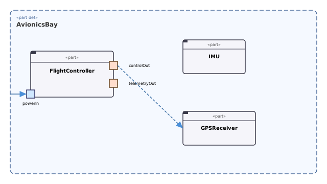
The avionics bay IBD shows three part usages — FlightController, IMU, and GPSReceiver — with ports and flow connections inside the AvionicsBay boundary.
Propulsion sub-system
The propulsion namespace defines an abstract PropulsionSystem with two concrete rotor configurations (QuadRotorConfig, HexRotorConfig), each typed by RotorAssembly. A RotorAssembly owns exactly one Motor.

Power sub-system
The power namespace defines PowerSystem as a PartDef with two parts — battery : BatteryPack and pdu : PowerDistributionUnit — connected by a PowerConnectionDef flow. The PDU's output port is bound to the system-level mainPowerOut boundary port.

Behavior
Mission execution is modelled under the Behavior namespace as a tree of ActionDef elements:
| Element | Type | Role |
|---|---|---|
MissionExecution | ActionDef | Orchestrates the three flight sub-actions |
TakeoffAction | ActionDef | Throttle ramp; altitude monitoring loop |
WaypointNavAction | ActionDef | GPS-guided waypoint traversal loop |
LandingAction | ActionDef | Descent; altitude monitoring; motor disarm |
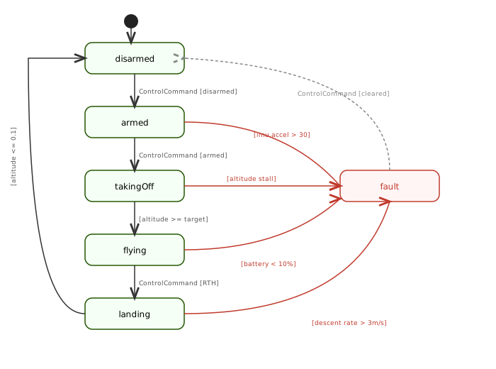
FlightStates | StateSpaceDef | Idle → Arming → Takeoff → Cruise → Landing → Disarmed |
Mission Execution Sequence
The sequence diagram below shows the full message flow for MissionExecution across the four participants.
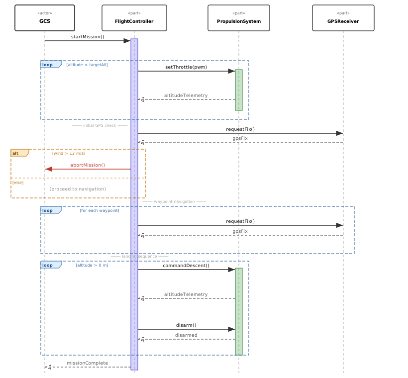
The diagram covers four combined fragments:
loop [altitude < targetAlt]— takeoff throttle ramp and altitude telemetry loopalt [wind > 12 m/s]— weather check; aborts the mission or continues to waypointsloop [for each waypoint]— GPS fix requests and waypoint advancementloop [altitude > 0 m]— descent monitoring, disarm, and mission-complete handshake
Flight State Machine
FlightStates models the UAV's operational lifecycle. Red transitions lead to the fault state; the gray dashed arc is the recovery path back to disarmed.
Diagrams
| Diagram | Kind | Subject |
|---|---|---|
| UAVSystemBDD | BDD | UAV::UAVSystem — top-level block decomposition |
| PropulsionSystemBDD | BDD | UAV::Propulsion — Motor / RotorAssembly composition |
| AvionicsBayIBD | IBD | UAV::Avionics::AvionicsBay — FC, IMU, GPS ports and flows |
| PowerSystemIBD | IBD | UAV::Power::PowerSystem — battery → PDU power flow |
| MissionExecutionSeq | Sequence | Behavior::MissionExecution — full mission message flow |
| FlightStatesMachineD | StateMachine | Behavior::FlightStates — flight phase state machine |
| SafetyRequirementsD | Requirement | Safety requirement / allocation / verification trace |
| RequirementTraceMermaid | Mermaid | Requirements — full traceability graph |
Requirements
Parent requirements
| ID | Title |
|---|---|
| REQ-UAV-SAFE-000 | UAV shall not cause injury to persons or property during any flight phase |
| REQ-UAV-PERF-000 | UAV shall meet mission performance objectives for endurance, navigation, and data link |
| REQ-UAV-REG-000 | UAV shall comply with all applicable regulatory requirements (sub-5 kg open category) |
Leaf requirements
| ID | Title | Domain |
|---|---|---|
| REQ-UAV-MASS-001 | Maximum take-off mass ≤ 5 kg | system |
| REQ-UAV-ENDUR-001 | Minimum 25-minute flight endurance under nominal conditions | hardware |
| REQ-UAV-NAV-001 | GPS position accuracy ≤ 1.5 m CEP under nominal GNSS | hardware |
| REQ-UAV-COMM-001 | Telemetry data link range ≥ 5 km line of sight | software |
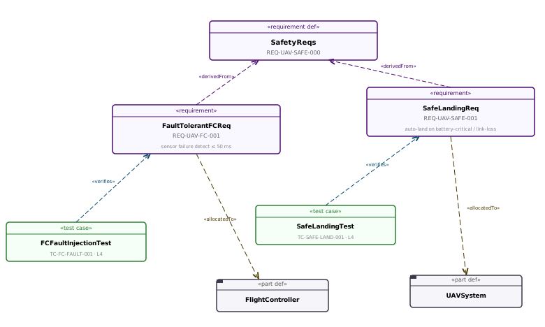
| REQ-UAV-FC-001 | Flight controller shall detect single sensor failure within 50 ms | software |
| REQ-UAV-SAFE-001 | Autonomous safe landing on battery-critical or link-loss event | software |
Each leaf requirement carries derivedFrom: pointing to its parent and breakdownAdr: referencing the ADR that justified the decomposition — enforced by validation rule E310.
Safety requirements trace
Verification
Sixteen test cases (under model/Verification/) cover the leaf and parent requirements: leaf requirements are verified at unit/system level, parent requirements by integration-level cases (L3–L5) plus a review. Each is a TestCase element with a stable TC-* ID, a testLevel (L1–L5), and a Gherkin scenario: block.
| File | Level | Verifies |
|---|---|---|
MassVerificationCase | L5 | REQ-UAV-MASS-001 |
EnduranceTestCase | L5 | REQ-UAV-ENDUR-001 |
NavigationAnalysisCase | L2 | REQ-UAV-NAV-001 |
DataLinkTestCase | L5 | REQ-UAV-COMM-001 |
FCFaultInjectionTest | L5 | REQ-UAV-FC-001 |
SafeLandingTest | L5 | REQ-UAV-SAFE-001 |
CargoReleaseTest | L4 | REQ-UAV-CARGO-001 |
MappingDensityTest | L4 | REQ-UAV-MAP-001 |
DualFCFailoverTest | L4 | REQ-UAV-REDUN-001 |
VariantIntegrationTest | L4 | REQ-UAV-VAR-000 |
MissionPerformanceIntegrationTest | L5 | REQ-UAV-PERF-000 |
SystemSafetyIntegrationTest | L5 | REQ-UAV-SAFE-000 |
RegulatoryComplianceIntegrationTest | L4 | REQ-UAV-REG-000 |
PerformanceCaseReview | L2 | REQ-UAV-PERF-000 |
SafetyCaseReview | L2 | REQ-UAV-SAFE-000 |
RegulatoryComplianceReview | L2 | REQ-UAV-REG-000 |
---|---|---| | MassVerificationCase | L1 (analysis) | REQ-UAV-MASS-001 | | EnduranceTestCase | L2 (ground) | REQ-UAV-ENDUR-001 | | NavigationAnalysisCase | L3 (simulation) | REQ-UAV-NAV-001 | | DataLinkTestCase | L2 (ground) | REQ-UAV-COMM-001 | | FCFaultInjectionTest | L4 (flight) | REQ-UAV-FC-001 | | SafeLandingTest | L4 (flight) | REQ-UAV-SAFE-001 | | PerformanceCaseReview | L1 (analysis) | REQ-UAV-PERF-000 | | SafetyCaseReview | L1 (analysis) | REQ-UAV-SAFE-000 | | RegulatoryComplianceReview | L1 (analysis) | REQ-UAV-REG-000 |
Architecture decisions
| ID | File | Status | Subject |
|---|---|---|---|
| ADR-SYS-SAFE-001 | SafetyDecompositionADR | accepted | Safety requirement decomposition strategy |
| ADR-SYS-PERF-001 | PerformanceDecompositionADR | accepted | Performance requirement decomposition strategy |
Interfaces and flows
| Element | Kind | Carries |
|---|---|---|
Interfaces::TelemetryPortDef | PortDef | Items::TelemetryPacket |
Interfaces::ControlPortDef | PortDef | Items::ControlCommand |
Interfaces::PowerPortDef | PortDef | Items::BatteryPower |
Interfaces::TelemetryConnectionDef | ConnectionDef | Telemetry flow GCS ↔ UAV |
Interfaces::PowerConnectionDef | ConnectionDef | DC power distribution |
Running the validator
The report covers every element (the element inventory is its first section), the full requirements traceability matrix, and any validation findings. The model produces zero errors; its warnings are deliberate, advisory findings. Note that model/ also hosts Syscribe's own product requirements, ADRs and planning items alongside the UAV, so the totals include those.